
您当前的位置:首页 » 产品展示 » 示波器探头/附件 » CT6电流探头,美国泰克CT6,泰克CT6电流探头
| 产品名称: | CT6电流探头,美国泰克CT6,泰克CT6电流探头 |
| 产品型号: | CT6 |
| 品牌: | |
| 产品数量: | |
| 产品单价: | 面议 |
| 日期: | 2024-09-19 |
CT6电流探头,美国泰克CT6,泰克CT6电流探头的详细资料
Features & Benefits
- High Bandwidth
- Ultra-low Inductance
- Very Small Form Factor
- Characterize Current Waveforms up to <200 ps Rise Times
- Very Low Loading of Circuit Under Test
- Fits Into Dense, Closely-spaced Circuit Designs
- Data Storage Read Channel Design
- Silicon Characterization
- High-frequency Analog Design
- ESD Testing
- Signal Injection
- Differential Current Measurements
- Single-shot Low Rep-rate Pulse Measurements
- Propagation Delay Measurement
CT6 Current Probe
The CT6 is the newest addition to the Tektro
CT1/CT2 Current Probes
The CT1 and CT2 Current Probes are designed for permanent or semi-permanent in-circuit installation. Each probe co
The P6041 Probe Cable provides the co
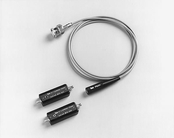
CT1/CT2. Current Probes with P6041 BNC Probe Cable.
Miniature Co
The CT1 and CT2 detachable cable design enables one or more probes to be located on circuit boards or in other limited space areas.
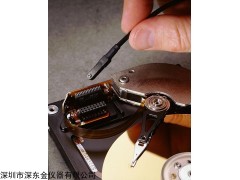
The CT6 offers the smallest form factor available, for measurement on ever-shrinking circuit boards and components. It is designed for temporary installation and does not incorporate removable cables, as the CT1 and CT2 do.
Extendible Probe Length
Specified rise time and bandwidth are obtained when using the probe cables provided: The P6041 cable used with the CT1 and CT2 is 42 inches nominal. If additio
The CT1 and CT6 provide an output of 5 mV for each milliamp of input current when terminated in 50 Ω. The CT2 provides 1 mV per milliamp when terminated in 50 Ω.
Typical SystemsCT6电流探头,美国泰克CT6,泰克CT6电流探头:
The CT1, CT2, and CT6 high-frequency current transformers are dynamic (i.e., non-DC) current measuring devices. They are typically used in co
The CT1 or CT2 can be used with 1 MΩ input systems; use the P6041 probe cable and terminate the output with a 50 Ω feed-through termination (see Optio
In all cases, the CT1, CT2, and CT6 must work into 50 Ωs to obtain specified performance and sensitivity.
CT6电流探头,美国泰克CT6,泰克CT6电流探头:
Most true-differential voltage amplifiers have a maximum bandwidth of a
In all cases, Derating with Frequency and Amp-second Product (Current-time Product) guidelines should not be exceeded. (See Characteristics.)
CT1 Typical Frequency Response.
These common measurements are easy to make with the CT1, CT2, or CT6 provided that your signal fits within the Max Pulse Current and Amp-second Product (Current-time Product) guidelines for the specific current probe characteristics.
For example, the CT2 is rated at 36 A peak, with an Amp-second Product of 50 × 10-6 seco
Two CT1 or CT2 Current Transformers with matching probe cables can be used to measure propagation delay (transit time) between the input and output currents of high-frequency devices. The probe outputs are co
Verification of any Probe/Cable/Scope System mismatch can be obtained by passing the same signal current through both probes and observing total system delay difference, if any.
CT1, CT2, and CT6 Characteristics
|
Characteristic |
CT1 |
CT2 |
CT6 |
|---|---|---|---|
|
Bandwidth (typical) |
25 kHz to 1 GHz |
1.2 kHz to 200 MHz |
250 kHz to 2 GHz |
|
Rise Time |
350 ps |
500 ps |
200 ps |
|
Sensitivity (into 50 Ω) |
5 mV/mA |
1 mV/mA |
5 mV/mA |
|
Accuracy |
±3% |
±3% |
±3% |
|
Magnetizing Inductance |
6 μH |
7 μH |
1 μH |
|
Leakage Inductance |
2.4 nH |
1 nH |
1.5 nH |
|
Insertion Impedance: |
|||
|
at 10 MHz |
<1 Ω |
0.1 Ω |
1.1 Ω |
|
at 100 MHz |
2 Ω |
0.5 Ω |
1.3 Ω |
|
at 1 GHz |
|
|
11.9 Ω |
|
Max. Bare Wire Size |
#14 wire |
#16 wire |
#20 wire |
|
1.78 mm (0.070 in.) |
1.32 mm (0.052 in.) |
0.8 mm (0.032 in.) |
|
|
Max. Bare Wire Voltage: |
|||
|
RMS |
175 VRMS CAT I |
175 VRMS CAT I |
30 VRMSCAT I |
|
Peak |
1000 V*1 |
1000 V*1 |
30 V |
|
DC |
175 V |
175 V |
30 V |
|
Max. Peak Pulse Current |
12 A |
36 A |
6 A |
|
Max. Co |
450 mA |
2.5 A |
120 mA |
|
Amp-second Product |
1 × 10⁻⁶ A*Sec |
50 × 10-6 A*Sec |
0.25 × 10⁻⁶A*Sec |
|
L/R Time Co |
>6.35 μs |
>160 μs |
0.4 μs |
|
Propagation Delay |
5.4 ns |
6.1 ns |
5.2 ns |
|
Safety |
UL3111-2-032, CSA1010.2.032, EN61010-2-032, IEC61010-2-032 |
UL3111-2-032, CSA1010.2.032, EN61010-2-032, IEC61010-2-032 |
NA |
*1 (<3.25% Duty Factor).